CISCO SPA504G
All information relating to the CISCO SPA504G 4-line IP phone.
Troubleshooting
Phone Does Not Boot
Well well well. You've bricked the phone. Well done.
This can happen when you become a little too curious about what the fmt commands do.
All is not lost, you can most likely recover the phone with a bit of effort.
Requirements
- Access to the phone's UART debugging interface
- A
tftpserver- I used the inbuilt one with
truenas.
- I used the inbuilt one with
- A copy of some firmware. (See
JackGit)
Steps
- Configure your tftp server and place the
.binfile from the firmware zip file inside the root directory. - Access the phone's UART debug interface
- Power on the phone.
- If the phone cannot boot it will enter into the bootloader (
PSPBoot) shell,psbl. - You should see something similar to this.
- NOTE: If you mistype a command the shell will hang and the device will need to be power cycled. This gets annoying fast. Good luck!
- If the phone cannot boot it will enter into the bootloader (
Basic POST completed... Success.
Last reset cause: Hardware reset (Power-on reset)
PSPBoot1.4 rev: 1.4.0.6
(c) Copyright 2002-2008 Texas Instruments, Inc. All Rights Reserved.
Press ESC for monitor... 1
(psbl)
-
Next set the following environment variables:
- The static IP Address of the phone:
-
setenv IPA 192.168.1.200
-
- The subnet mask:
-
setenv SUBNET_MASK 255.255.255.0
-
- The MAC address:
-
setenv HWA_0 aa:aa:aa:aa:aa:aa
-
- The MAC port:
-
setenv MAC_PORT 0
-
- I'm not 100% sure you need to do this but I haven't checked.
- The static IP Address of the phone:
-
You should be ready to upgrade the firmware.
-
upgrade -i <TFTP_SERVER_IP> spa50x-30x-7-4-6.bin
-
-
If successful, you'll see the new firmware be written to memory.
(psbl) upgrade -i 192.168.1.5 fw.bin
Validate firmware successful
Cannot upgrade bootloader in bootloader/recovery
Cannot upgrade bootloader in bootloader/recovery
Programming sector:3
Programming sector:4
Programming sector:66
Programming sector:67
Programming sector:68
Programming sector:69
Programming sector:70
Programming sector:71
Programming sector:72
...
Programming sector:125
Programming sector:126
Programming sector:127
- Finally, reboot the phone by either:
- Power cycle
-
reboot
You will know the process will have worked when you see something like this:
Booting...
Attached TCP/IP interface to dummy unit 254
Attaching network interface lo0... done.
Adding 8763 symbols for standalone.
CPU: TI TNETV1057 Communication Processor. Processor #0.
Memory Size: 0xffe000. BSP version 7.2.7.20.
========================================================
Board : TI TNETV1057 Communication Processor
SOC : Titan, ChipId: 0x7, Version: 2
Cache : Write-Back, Write-Allocate
PSP Version : 7.2.7.20
Type : BasePSP 7.2.7.20 Patch
PSPWIZ Version : 0.5
MIPS freq : 87500000 Hz,
System Freq : 87500000-> Hz,
VBUS freq : 81250000 Hz
BasePSP mode : Routing
========================================================
Model no: 2
appCreate: autoBootLevel=2
MXP environment is created.
About to create Idle Task
About to create Measurement Task
Idle Measurement Tasks created
Panic button enabled
Heartbeat started
Creating Golden Gateway application...
Creating fs:/tmp 3145728
Decompress app module.... done
appmodule len=2642000
Creating fs:/DR 16384
/DR created
decompress constdat successfully:520624
flash_init . . .
-- flash_raw_init . . .
-- flash_fstr_init . . .
-- flash_fsm_init . . .
-- flash_license_init . . .
-- flash_fpar_init . . .
-- flash_custom_init . . .
-- flash_fprv_init . . .
-- flash_dhcp_prov_init . . .
flash_init done
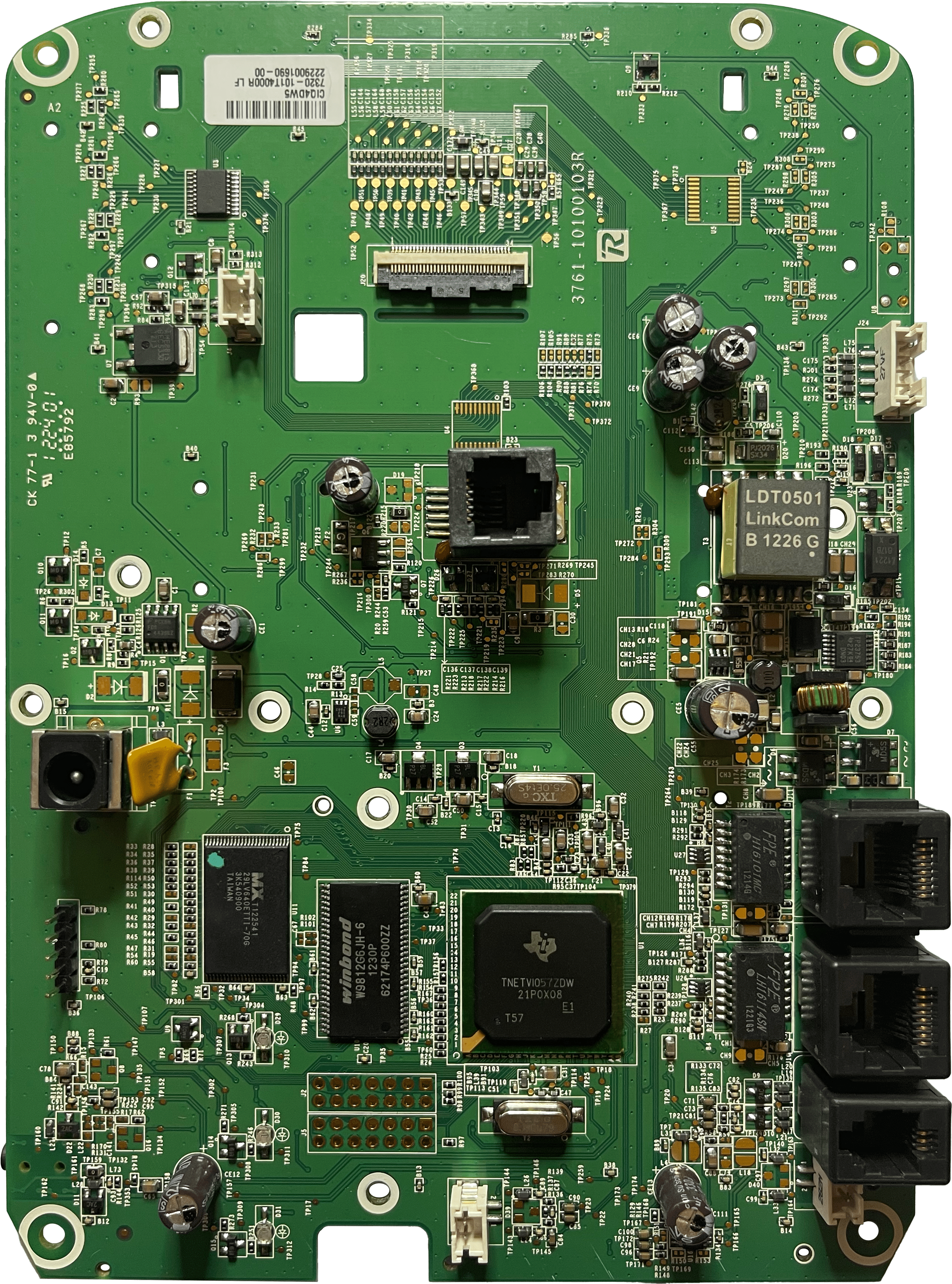
Hardware
Board overview
UART serial
Once removing the case, there is a five pin header on the rear of the device. Four of the five pins are used. This is pictured below.
The SPA504G's UART serial header operates using the following configuration:
- +3.3 V
- 9600 baud
- flow control disabled
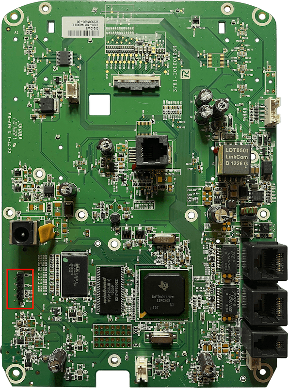
The pinout is shown below.

Titan SoC
The SPA504G uses the Texas Instruments TNETV1057ZDW processor on a Titan SoC, pictured below.
It is super hard to find a datasheet for this CPU/SoC; however, the boot logs reveal that the CPU operates at 87.5 MHz, and the SoC features 60 KB (61.44 KiB) of memory. A datasheet for a similar CPU from the same series / era can be found here.
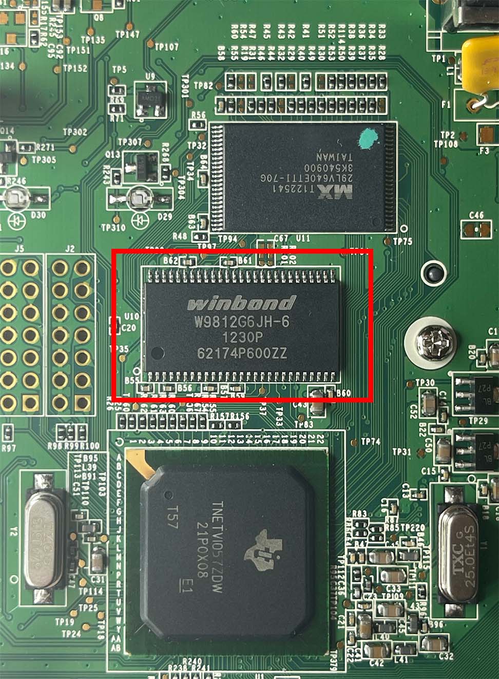
Extra memory banks are provided on the SPA504G's PCB. These are detailed here.
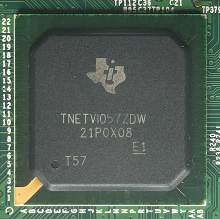
This CPU uses a MIPS instruction set.
Memory
Extra memory (beyond what is provided on the SoC) is provided through the W9812G6JH-6 IC, manufactured by Winbond. The datasheet for this IC can be downloaded from here.
This IC offers 16 MB of volatile memory (2,097,152 words x 4 banks x 16 bits), and operates at a frequency of 166 MHz (CL3).
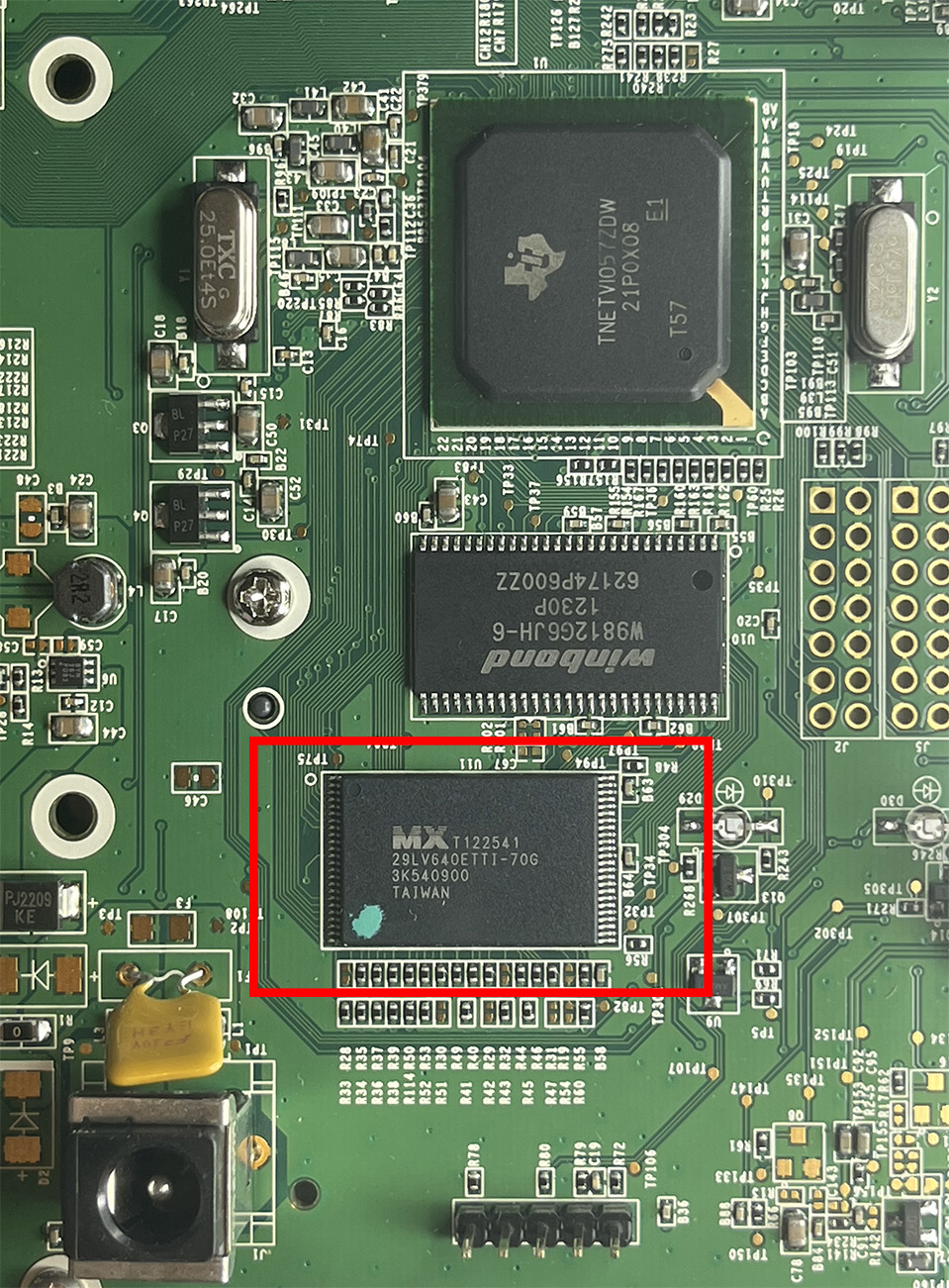
Flash storage
Whilst no information could be found online regarding the MX T122541 IC, Macronix is semiconductor manufacturer which specialises in producing non-volatile memory.
It is likely that there are JTAG headers on the SPA504G. Maybe we can identify more about this IC using that...?
Software
Serial boot logs
When connecting to the UART serial header, the following is printed to the console during boot:
Basic POST completed... Success.
Last reset cause: Hardware reset (Power-on reset)
PSPBoot1.4 rev: 1.4.0.6
(c) Copyright 2002-2008 Texas Instruments, Inc. All Rights Reserved.
Press ESC for monitor... 1
(psbl)
Booting...
Attached TCP/IP interface to dummy unit 254
Attaching network interface lo0... done.
Adding 8764 symbols for standalone.
CPU: TI TNETV1057 Communication Processor. Processor #0.
Memory Size: 0xffe000. BSP version 7.2.7.20.
========================================================
Board : TI TNETV1057 Communication Processor
SOC : Titan, ChipId: 0x7, Version: 2
Cache : Write-Back, Write-Allocate
PSP Version : 7.2.7.20
Type : BasePSP 7.2.7.20 Patch
PSPWIZ Version : 0.5
MIPS freq : 87500000 Hz,
System Freq : 87500000-> Hz,
VBUS freq : 81250000 Hz
BasePSP mode : Routing
========================================================
Model no: 2
appCreate: autoBootLevel=2
MXP environment is created.
About to create Idle Task
About to create Measurement Task
Idle Measurement Tasks created
Panic button enabled
Heartbeat started
Creating Golden Gateway application...
Creating fs:/tmp 3145728
Decompress app module.... done
appmodule len=2770028
Creating fs:/DR 16384
/DR created
decompress constdat successfully:521344
flash_init . . .
-- flash_raw_init . . .
-- flash_fstr_init . . .
-- flash_fsm_init . . .
-- flash_license_init . . .
-- flash_fpar_init . . .
-- flash_custom_init . . .
-- flash_fprv_init . . .
-- flash_dhcp_prov_init . . .
flash_init done
0000008654 - DSPALLOC: AER instance 1, max_tail = 60 ms, usage = ( HS HeS GL_HS GL_HeS )
0000008654 - DSPALLOC: AER instance 0, max_tail = 200 ms, usage = ( HS HeS HF GL_HS GL_HeS )
Boot Loader
The SPA504G uses the PSPBoot boot loader. This is an old bootloader with not much info out there but there is one piece of documentation floating arround and can be found here.
The bootloader can be found in the firmware update files: psbl.elf
Recovery Mode
There is also a recovery mode the device will boot into if it cannot load the bootloader. This is a minimal version of PSPBoot.
This recovery mode can be manually entered into at device boot by pressing esc when prompted with Press ESC for monitor....
PSPBoot1.4 rev: 1.4.0.6
(c) Copyright 2002-2008 Texas Instruments, Inc. All Rights Reserved.
Press ESC for monitor... 1
(psbl) help
reboot version info fa
printenv setenv setpermenv unsetenv
defragenv fmt fmtkosmos boot
dm oclk help ls
df cp cat rm
tftp upgrade
(psbl)
Firmware validation
The logic to validate the firmware bundle begins at: libupg_validate_firmware_mem.
This is called from libupg_upgrade_mem that is subsequently called from the command upgrade in the psbl terminal.
This can be seen from the upgrade command handler:
int upgrade(int argc,char **argv)
{
int iVar1;
undefined4 *param2;
if ((argc == 2 || argc == 4) && ((argc != 4 || (iVar1 = strcmp(argv[1],"-i"), iVar1 == 0)))) {
*argv = "upgrade";
argv[argc] = "/dev/ram";
param2 = (undefined4 *)tftp(argc + 1,argv); // [1]
if (0 < (int)param2) {
iVar1 = libupg_upgrade_mem((astruct *)0xb4500000,param2); // [2]
return iVar1;
}
}
else {
upgrade_usage();
}
return -1;
}
A couple of things to note from this snippet:
- [1] Shows the data is being obtained through
tftp(wtf) - We can see the address [2]
0xb4500000being passed intolibupg_upgrade_mem. This will be the location that the firmware is either downloaded to or where we will begin flashing.
libupg_validate_firmware_mem
The function starts by taking two arguments:
int libupg_validate_firmware_mem(byte *param1,uint param2)
[...]
-
param1is the pointer into RAM discussed above (0xb4500000) -
param2is the result fromtftp(Looks like it is being used as a data length)
The function begins by validating the firmware's header.
Header validation
The header validation can be found in function validate_firmware_header.
The function starts by taking a structure (we're going to call it firmware_header_struct).
The function contains two stages:
- Digest validation
- Randseq validation
Information regarding the "header format" has been split into a separate page. Please see Firmware format for more information. The rest of this section wiill use terminology sourced from it.
Digest validation
To calculate the digest you perform the following:
- Zero out the Signature
- Zero out the Digest
- MD5 hash of the firmware header and module header table.
The size of the headers is calulcated with the formula below:
size = hdr->FirmwareHeaderSize + hdr->NumberOfModules * hdr->ModuleHeaderSize;
The process listed above can be seen in the following tidy Ghidra decompilation (Note: The size parameter is the one calulcated above)
int gen_fmhdr_digest(void *md5_struct_out, firmware_header_struct *fm_hdr, size_t size) {
byte *pDigest;
byte *pSignature;
astruct_1 MD5Buffer [3];
undefined lSignature [32];
undefined lDigest [16];
// Save signature and digest
pSignature = fm_hdr->Signature;
memcpy(lSignature,pSignature,0x20);
pDigest = fm_hdr->Digest;
memcpy(lDigest,pDigest,0x10);
// Zero signature and digest
memset(pSignature,0,0x20);
memset(pDigest,0,0x10);
// MD5 time
MD5Init(MD5Buffer);
MD5Update(MD5Buffer,fm_hdr,size);
MD5Final(md5_struct_out,MD5Buffer);
// Restore signature and digest
memcpy(pSignature,lSignature,0x20);
memcpy(pDigest,lDigest,0x10);
return 0;
}
Randseq validation
To calculate the Randseq perform the following:
- Zero out the Signature, Digest and Ranseq elements of the header
- Perform the
nsdigeston the same data as the MD5 digest above.nsdigestdoes the following:- For each 0x20 sized block in the firmware header and module header table:
- For each byte:
- Get the value from the byte array and add a special counter. Place this result of the addition into a temp buffer array
- Increment counter by 0x19
- Pass the 32 byte arrary into MD5Update
- For each byte:
- Repeat until all bytes have been processed
- For each 0x20 sized block in the firmware header and module header table:
This process can most clearly be seen with the following Python script:
import hashlib
SIGNATURE_OFFSET = 16
DIGEST_OFFSET = 48
RANDSEQ_OFFSET = 64
def memset(data, start, size):
temp_data_mutable = list(data)
for i in range(size):
temp_data_mutable[start+i] = 0
return bytes(temp_data_mutable)
def nsdigest(data, size):
data_index = 0
addition_value = 0
buf = [0] * 0x20
md5 = hashlib.md5()
while True:
buffer_index = 0
while True:
buf[buffer_index] = (data[data_index] + addition_value) & 0xff
addition_value += 19
buffer_index += 1
data_index += 1
if buffer_index >= 0x20 or data_index >= size:
break
md5.update(bytes(buf))
if data_index >= size:
break
return md5.digest().hex()
def main():
with open("spa50x-30x-7-6-2g.bin", "rb") as f:
data = f.read()
# Calculates the size of the headers
size = 0x80 + (0x4f * 0x40)
data = memset(data, SIGNATURE_OFFSET, 32)
data = memset(data, DIGEST_OFFSET, 16)
data = memset(data, RANDSEQ_OFFSET, 16)
x = nsdigest(data, size)
print(x)
if __name__ == "__main__":
main()
Firmware format
The firmware file is made up of the following components, each located in the firmware file after one another:
- Firmware header
- Module header table
- Module data
This can be extracted using the following Kaitai Struct definition:
Kaitai Struct definition
meta:
id: spa504g
endian: be
license: Butlersaurus
title: SPA504G firmware
bit-endian: be
seq:
- id: header
type: header
- id: modules
type: module
repeat: expr
repeat-expr: header.module_count
types:
header:
seq:
- id: magic
contents: SkOsMo5 fIrMwArE
- id: signature
size: 32
- id: digest
size: 16
- id: random_sequence
size: 16
- id: header_length
type: u4
- id: module_header_length
type: u4
- id: file_length
type: u4
- id: version
type: str
encoding: utf8
size: 32
- id: module_count
type: u4
- id: padding
size: header_length - 128
module:
seq:
- id: module_sequence_number
type: u2
- id: module_compressed_flag
type: u2
- id: module_length
type: u4
- id: module_offset
type: u4
- id: module_digest
size: 16
- id: padding
size: _parent.header.module_header_length - 28
instances:
body:
pos: module_offset
size: module_length
process: zlib
Firmware header
The firmware header is located at the very beginning of the file. Its length is defined by the 32 bit unsigned integer (big endian) located at offset 0x0050. For example: 0x00000080 (128 bytes).
The format for the firmware header is described below:
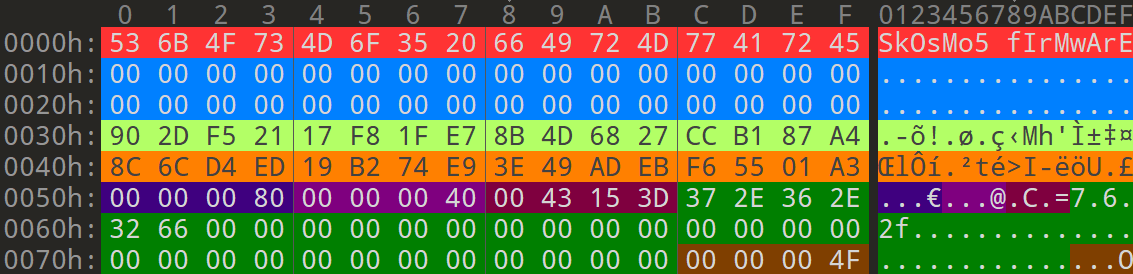
| Size (byte) | Type | Description | Example |
|---|---|---|---|
| 16 | Byte array | Identifier | SkOsMo5 fIrMwArE |
| 32 | Byte array | Signature | Not used |
| 16 | Byte array | MD5 of firmware header + module headers | 90 2D F5 21 17 F8 1F E7 8B 4D 68 27 CC B1 87 A4 |
| 16 | Byte array | A random sequence | 8C 6C D4 ED 19 B2 74 E9 3E 49 AD EB F6 55 01 A3 |
| 4 | Unsigned BE Int | Length of the entire firmware header | 0x00000080 (128 bytes) |
| 4 | Unsigned BE Int | Length of each module header | 0x00000040 (64 bytes) |
| 4 | Unsigned BE Int | Length of entire file | 0x0043153D (4396349 bytes) |
| 32 | Byte array | Firmware version number | 7.6.2f |
| 4 | Unsigned BE Int | Number of modules present in the firmware | 0x0000004F (79 modules) |
Module header table
There are multiple modules in the firmware file. The number of modules is defined at offset 0x007C in the firmware header. For example: 0x0000004F (79 modules).
Each module has a module header, located in a module header table. These are of a length defined at offset 0x0054 in the firmware header. For example: 0x00000040 (64 bytes). Each module header is concatenated in order, directly after the firmware header (in this case, from offset 0x0080).
The format for each module header is described below. The screenshot contains three of the 79 module headers present in this particular firmware (7.6.2f).
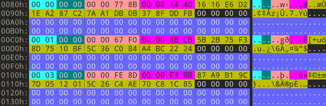
| Size (byte) | Type | Description | Examples |
|---|---|---|---|
| 2 | Unsigned BE Short | Sector ID | 0x00 (0) 0x01 (1) 0x03 (3) This was observed to increase from 0 to 127, skipping the following values:
|
| 2 | Unsigned BE Short | Compressed flag? | 0x00 |
| 4 | Unsigned BE Int | Length of module data | 0x0000778B (30,603 bytes)0x000067F0 (26,608 bytes)0x0000FE8D (65,165 bytes)... |
| 4 | Unsigned BE Int | Offset to module data from start of file | 0x00001440 (5,184 bytes)0x00008BCB (35,787 bytes)0x0000F3BB (62,395 bytes)... |
| 16 | Byte array | MD5 digest of the uncompressed module | 16 16 E6 D2 1E A2 87 C2 7A A1 DB 0B 37 8F DD FB5B 2B 75 F3 8D 75 10 BF 5C 36 C0 84 A4 BC 22 2487 A9 B1 9C 7D 05 12 01 5C 26 C4 AE 70 C8 1C 85... |
| 4 | Byte array | Unknown | |
| 32 | Padding | Zero padding |
Module data
The offset and size for each module's data is defined in the corresponding module header in the module header table.
For example, the first module in this particular firmware (7.6.2f) is located at offset 0x00001440 (5,184 bytes) from the beginning of the file, and is 0x0000778B (30,603 bytes) long.
It looks like all of this data is zlib compressed with a 'windowBits' parameter of 15, as determined by reversing the 'uncompress' method in the psbl.elf binary.

Using Python, these can be deflated trivially. A PoC deflation script is shown below:
Python deflate script
import zlib
compressed_data = open('spa50x-30x-...-module.bin', 'rb').read()
decompressed_data = zlib.decompress(compressed_data, 15) # windowBits of 15.
with open('spa50x-30x-...-module_deflated.bin', 'wb') as f:
f.write(decompressed_data)
Firmware artefacts
Extracted using the SPA504G extraction utility available here.